Underground Utility Survey using GPRWe are Goodland Survey, a company that offers Ground Penetrating Radar Survey, Mobile LiDAR Survey, Drone LiDAR Survey, Drone Photogrammetry Survey, DGPS Survey, Total Station survey and Fly Level survey. We have 20 years of experience with more than 5 million INR turnover, every year. If you need a survey done, we are the company for you. We have the latest and most advanced equipment, and our surveys are always accurate. Contact us today to get a free quote. Goodland equipped with Mala Multi frequency GPR, Leica Pegasus:Two LiDAR, GreenValley International LiAIR V70 Aerial LiDAR, DJI Mavic 3E PPK Photogrammetry Drone, Trimble Spectra Precision DGPS, Sokkia Total Station amd Sokkia Auto Level 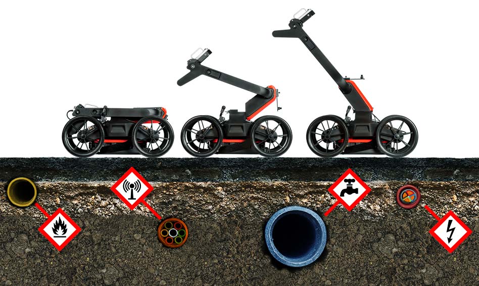
0 Comments
Leica Pegasus:Two Mobile Sensor PlatformSurvey Grade accuracy & vehicle-independent mobile mapping solution

The Leica Pegasus:Two mobile mapping solution have a laser scanner in combination with GNSS receivers, IMU and a DMI. It acquires accurate and precise spatial data with six to eight cameras on any vehicle. This innovative mobile sensor platform will not only capture point cloud and imaging data but also collects data from additional sensors. Sky or pavement assessment cameras, noise pollution sensors, air quality sensors or ground penetrating radar (GPR) for underground asset mapping all leverage the concept of a multiple sensor platform.
Case Study - 1Final Location Survey for Erode - Karur - Dindigul, 140 Kms

140 Kms of Railway Track scanned for "Final Location Survey for doubling of existing railway track in the section of Erode-Karur-Dindigul Railway Station" and the topographic baseplan, design, estimation are delivered withing 45 days of time.
Establishing of Ground Control Points is taken 12 working days, LiDAR survey takes 4 to 5 hours, Physical field verification took 10 days. And the data processing, designing , estimating are prepared and submitted in 20 working days. Overall primary survey data, designs and estimates are delivered withing 45 days of time. 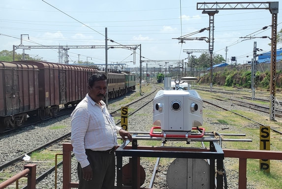
Deliverables: (a) LiDAR Point Cloud Data (b) 360 Degree Spherical Images at every 5 meters interval (c) Working Plan, (d) Working Section, (e) Index Plan, (d) Index Section, (e) Major & Minor Bridges Designs, (f) ROB, RUB, FOB designs, (g) Yard Plan & sketches, (h) Cross Section drawing at every 50 meters interval, (i) Estimate & Report
Case Study - 2Delhi - Palwal - Agra National Highway

Surveying and preparing topographic drawing for Delhi-Agra Highway, 180 kms which is scanned for multiple run (Road left, right, service roads, approach roads and under bridge scanning) took 7 days of field work and 30 days of data processing and CAD file preparation. Establishing of Ground control points was done in 20 days. All deliverables are submitted within the time frame.

Type of ApplicationsWe use the instrument for Highways, Railway, City Survey, and Metro Rail Projects. We help the consultants and contractors for...
A surveyor should have a basic understanding of the derivation of this grid system and the relationship of the various components of the Transverse Mercator Projection. In most cases, inverses computed from grid coordinates do not correspond to measured values in the field. The surveyor must understand why the discrepancy exists and properly apply the necessary corrections so that field measurements and coordinate geometry computations are consistent. Thus, it is important to understand the relationship between a point on the topography and its representation on the state plane coordinate system. What are coordinates?A coordinate system is a method for identifying the location of a point on the earth. Most coordinate systems use two numbers, a coordinate, to identify the location of a point. Each of these numbers indicates the distance between the point and some fixed reference point, called the origin.  What is the UTM Coordinate System?The UTM (Universal Transverse Mercator) coordinate system divides the world into sixty north-south zones, each 6 degrees of longitude wide. UTM zones are numbered consecutively beginning with Zone 1. Within each zone, coordinates are measured as northings and eastings in meters. The northing values are measured from zero at the equator in a northerly direction. Each zone has a central meridian that is assigned an easting value of 500,000 meters. Official Definition: https://pubs.usgs.gov/fs/2001/0077/report.pdf Universal Transverse Mercator (UTM) Projection
A UTM zone is a 6° segment of the Earth. Because a circle has 360°, this means that there are 60 UTM zones on Earth. (360 ÷ 6 = 60).  UTM applies a secant cylinder that intersects the ellipsoid along two small circles parallel to the central Meridian. This means that the scale is constant north-south along the Meridians. But scale varies east-west along parallels. The two small circles are 180 kilometers east and west of the central Meridian at the Equator. The small circles have a scale factor of 1, meaning a distance of 100 meters in the ellipsoid would be the same on the map projection. The centerline of a UTM grid zone has a scale factor of 0.9996. This means that a distance of 100 meters on an ellipsoid would be 99.96 meters on a map. UTM projection distortions: The UTM projection minimizes distortion within that zone. So this means that when you want to show features in several UTM zones, it starts becoming a poor choice of map projection. Distortion is small near the central meridian, and as you move away it worsens. So this makes it most fitting for narrow regions Whis is Ground (or) Plane Coordinate System: In order to make the coordinate system usable for engineering projects, the horizontal relationships should be defined as two dimensional on one (mapping) plane. To make the coordinate system usable and to simplify linear measurement, the coordinate system should be rectangular so that equal values measured from a datum axis form a parallel line with that axis. Parallel lines to each of the two axes form a "grid" and the intersection of those lines are rectangular "grid coordinates". This type of coordinates is called Cartesian coordinate systems. The following table summarizes the differences between plane and ellipsoidal (UTM) coordinates 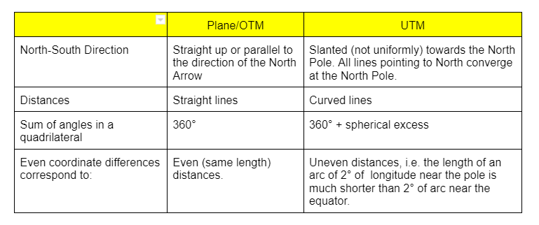 If the UTM coordinate system is adopted for Highway or any other projects, Total Station traverse closure accuracy will be 1:2500 or lesser. This will not meet the IRC Standards. (as per IRC, 1:10000 / 1:20000 accuracy required. ConclusionIn the geodetic reference system, coordinates of points (latitudes and longitudes) and the lengths and azimuths of lines are defined on an ellipsoid. Therefore, surveys that are to be adjusted to stations of the national control network must first be reduced to the ellipsoid. Since the state plane coordinate systems are developed directly from geodetic values, the use of those systems require the further reduction of the ellipsoid values to grid values. The reduction from ground to the state plane is a simple two-stage process. Reduction from ground to the ellipsoid is called the "elevation factor" and reduction from the ellipsoid to the state plane grid is called the "scale factor”. The scale factor at the central meridian is set to 0.9996 and it increases as a function of easterly or westerly distance of the point from the central meridian. The maximum value of the scale factor is 1.0001.
If the highway projects are surveyed (or) designed on UTM or any other ellipsoid based coordinate system, it will not match while the contractor is setting out the design at site with a Total Station. Even the control points will not match because of the scale factor & elevation factor. |
AuthorGoodland Team ArchivesCategories |


 RSS Feed